
Exlar Products
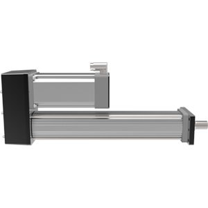
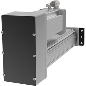
Universal Linear Actuators
Integrated Motor | Actuators
Intelligent Drive | Motor | Actuators
Rotary Actuators
Exlar Legacy Product Support
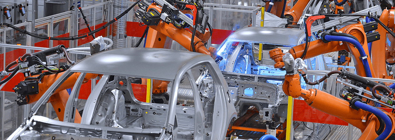
Industries
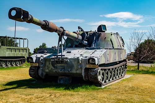
Automotive / EV Battery / Pressing
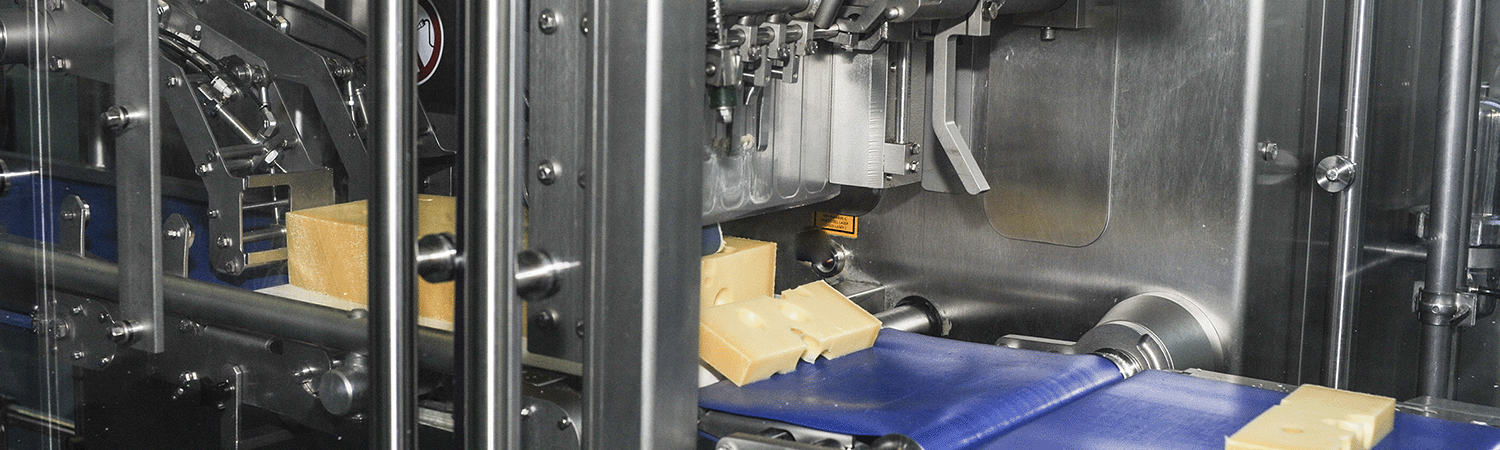
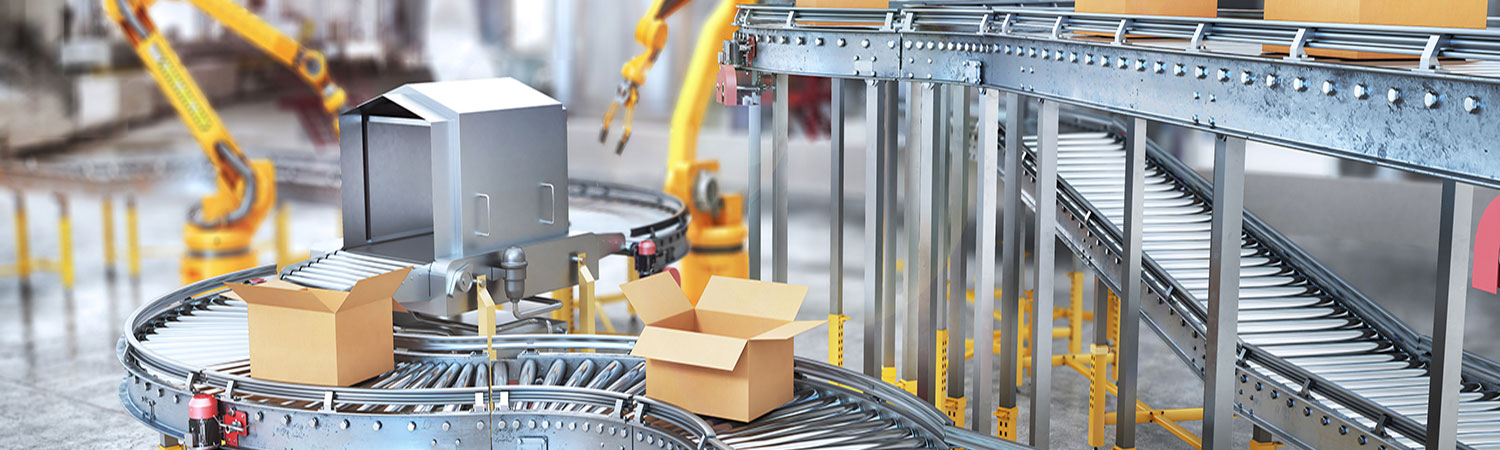
Food & Beverage / Packaging
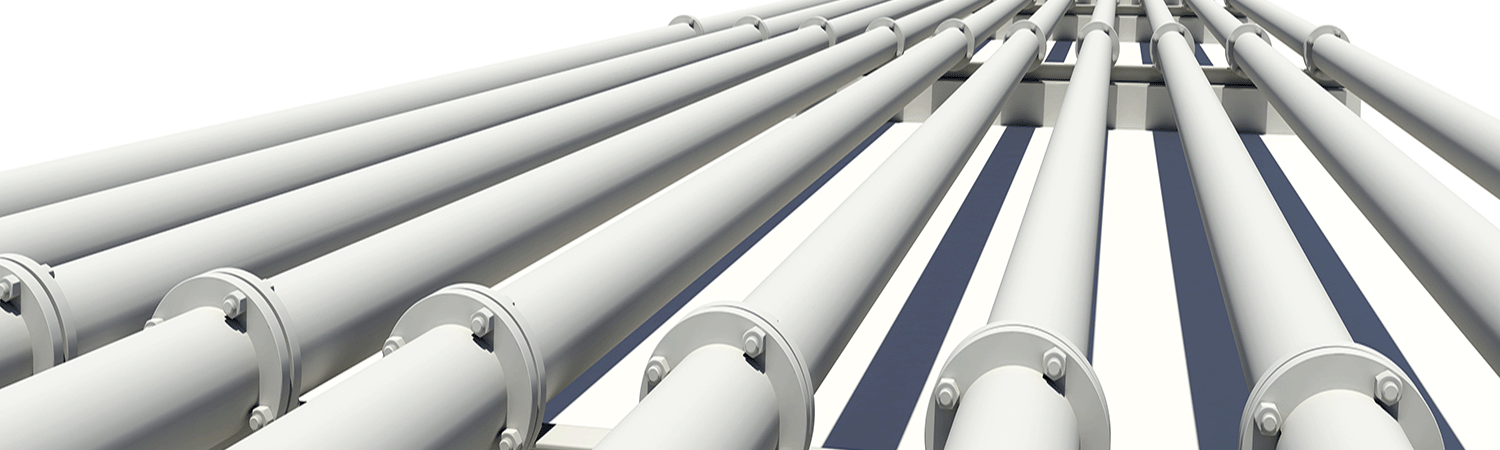
Oil & Gas
Plastics
Forestry
Entertainment / Simulation
Other Industries


.jpg?lang=en-GB)
.jpg?lang=en-GB)
.jpg "FT60-Critical-Speed-(2).jpg")
.jpg "FT60-Max-Force-(1).jpg")
.jpg "FT60-Series-Life-Curves-(1).jpg")
.jpg "FT60A-Series-Life-Curves-(1).jpg")
.jpg "FT80-Critical-speed-(1).jpg")
.jpg "FT80-Max-Force-(1).jpg")
.jpg "FT80-Series-Life-Curves-(1).jpg")
.jpg "FT80A-Series-Life-Curves-(1).jpg")