Utilizing a roller screw drive train, the Tritex EVA exceeds ISO22153 class D performance with little to no maintenance, and will last for years.
When comparing actuator price to actuator price this is true. But If you compare the entire system price of a no-emissions actuation solution to a pneumatic system, electric actuators can be the more cost-effective solution.
The Tritex EVA electric valve actuator is as fast as pneumatic actuators, opening and closing in as little as one second.
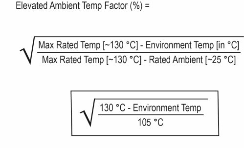
The answer is in terms of a percentage of the catalog rated continuous force.
Example:
Let’s say your environment is at 150°F and you’re using a GSX50-1010, 2-stack. The actuator has a continuous force rating of 1005 lbf, meaning at room temperature it could push 1005 lbf continuously without overheating. But you’re not operating at room temperature. You’re operating at 150°F.
So first, let’s convert to Celsius:
150°F = 65.56°C
Then let’s plug it into the equation:
This means you’re now limited to 78.3% of the original 1005 lbf rating. So 78.3% of 1005 lbf is 787 lbf. Your drive must now be programmed to limit to the current that is equivalent to this force if it were to be run continuously.
*You could still run at more current/force than this for a percentage of the time, just not 100%. For help calculating your allowed percentage based on run time, see our Duty Cycle Tip.
**Remember, this applies to actuators with motors in them, not stand-alone actuators. The calculation above still needs to be run for the motors controlling these actuators, and those motors still need to be limited if necessary, but the stand-alone (universal) actuators ratings are their rating regardless of temperature. i.e.: An FTX095 could push 5000 lbf at 25° C or 85° C as long as the motor could handle it.
Below is the maximum-allowable duty cycle for your application given the percentage of input current over the continuous current rating:
For example: If your actuator has a continuous current rating of 10 A and a continuous force rating of 1000 lbf, this means it will take about 10 A to produce 1000 lbf of force, or 5 A to produce 500 lbf of force, and so on. What if you need to push more than 1000 lbf? In most cases, you would look at a stronger stator or a larger actuator. What if it’s only for a few seconds? Could you over-work the current actuator? Well the answer is yes, and calculating by how much isn’t too difficult.
Let’s say you need to push 1500 lbf. This would be equivalent to 1.5x the continuous current rating of 10 A. If you look below, the graph recommends no more than a 22% duty cycle in this case. This means you can run the actuator 22% of the time at 15 A without overheating. The other 78% of the time, it needs to be off/cooling.
How long can you run at peak current?
Not a simple question, nor a simple answer. In reality, so many things affect this (how the system is built and how well the actuator is able to dissipate heat, are there additional heat sinks, particles in the air, degree of vacuum, new starting temp each time? (i.e. doesn’t always start from cold, etc.). Therefore, accurate times and temperature are quite difficult to estimate.
For example: At peak current (2x Continuous), the allowable duty cycle is 4%. That doesn’t mean you can run for 4 hours straight as long as you have 96 hours of off time in between however. From experience, a good rule of thumb we’ve estimated is 30s to a minute of peak current run time. Try to keep it under that, and then of course allow it to cool for the other 96% of the time.
We lubricate the seals on the front and rear of our FTX Series actuators upon initial assembly. However, the front seal gland should have a small amount of PTFE based lubricant applied to it periodically depending on the amount of use to keep the seal operating smoothly and to prolong the life of the actuator. Below are step by step instructions how to service or replace the front seal in the field.
We are asked about re-lubrication intervals a lot. The reality is that there is no generic interval to re-lube actuators. It depends on so many things and every application and situation is different, it is nearly impossible to accurately calculate a re-lube interval per application. So instead, we have a rough guideline table (shown below) to give users an idea on when to start checking for old contaminated grease that needs to be replaced. However, since ambient temperature, heat dissipation, speed variation, particles in the air, etc. can vary so much from application to application, this is only a guideline. The actuator should be checked more frequently around the period this table suggests and once it is noticed that the grease is ready to be replaced (Dirty, contaminated / very dark, filled with particles / debris) – a re-lube interval can be determined.
Remember, grease needs to be cleaned out and replaced – don’t just insert more. (Except for FTX’s, those can handle 5-6 greasings before they need to be cleaned out)
RMS ROTATIONAL SPEED (RPM) | RECOMMENDED GREASE RENEWAL PERIOD (HOURS) |
---|---|
250 | 10,000 |
500 | 10,000 |
1000 | 8000 |
1500 | 7000 |
2000 | 5800 |
2500 | 5000 |
3000 | 4000 |
A very common question for us. For the actuator itself, that is easy. There is a mechanical lead accuracy of the screw, which is usually 0.001 in/ft, a typical specification for precision positioning screws of any type. This means that at any point over the cumulative length of the screw, the lead will vary by a maximum of 0.001 inches per foot of screw length. This is not the same as mechanical repeatability. The mechanical repeatability is a tolerance on how close to the same linear position the screw will return, if approaching from the same direction, and driven exactly the same number of turns. This value is approximately 0.0004 inches.
The electronic positioning resolution is a function of the feedback device and the servo amplifier. Let’s assume that we have Exlar’s standard encoder on a GSX30 with 0.2 inches per revolution lead on the roller screw. Exlar’s standard encoder has 2048 lines and 8192 electronic pulses per revolution that it outputs to the servo drive. So in a perfect world, the positioning resolution would be (0.2 in/rev)/ (8192 pulses/rev) or 0.0000244 inches. Anyone who has used servo drives knows that you can’t position to one encoder pulse. Let’s use 10 encoder pulses as a reasonable best positioning capability. This gives us a positioning resolution of 0.000244 inches.
More things to consider: When addressing repeatability and accuracy, several things must also be taken into account. One of these is the stiffness of the system. Stiffness is how much the system will stretch or compress under compressive or tensile forces. If the combination of the stiffness of the actuator and the stiffness of the mechanical system, including all couplings, mounting surface, etc. allows for more compression or stretch than the required positioning resolution of the system, obtaining acceptable positioning results will be nearly impossible. Another consideration is thermal expansion and contraction. Consider a GS actuator attached to a tool that is doing a precision grinding process. Assuming that the tool is steel and 12 inches long, a 5 degree rise in temperature will cause the tool to expand by 0.0006 inches. If the system is programmed to make 0.0002 inch moves, this expansion could cause serious positioning problems. The same applies to the components of the actuator itself. The actuator rod can change in temperature from a cold start up to running temperature. This change may need to be accounted for in very precise positioning applications.