Exlar Produkte
Universelle Linearantriebe
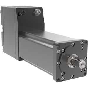
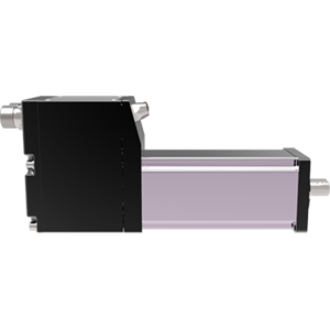
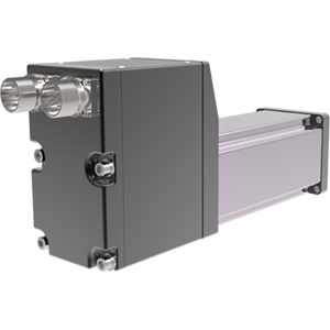
Integrierte Motor-| Aktoren
Intelligent Drive | Motor-| Aktoren
Drehantriebe
Industrien
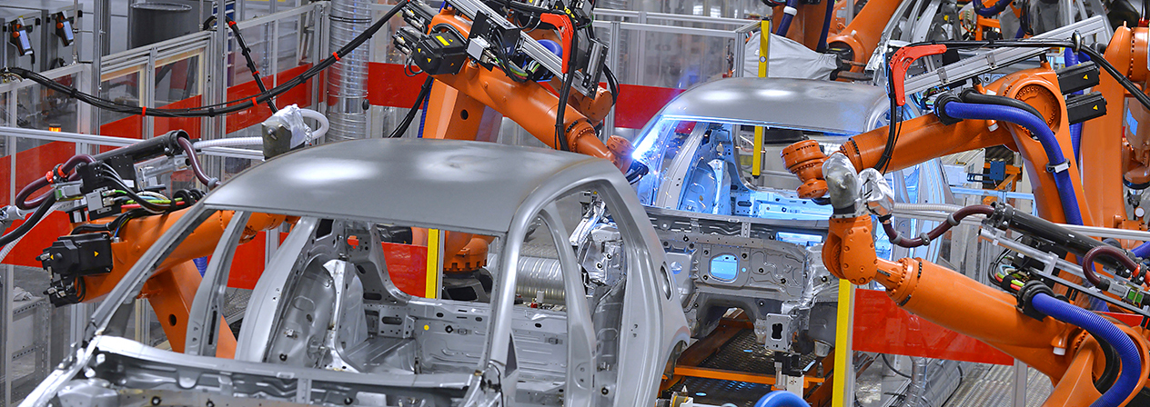
Automobil-/EV-Batterie
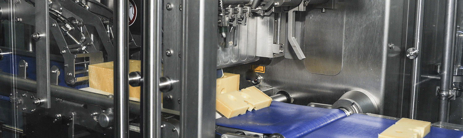
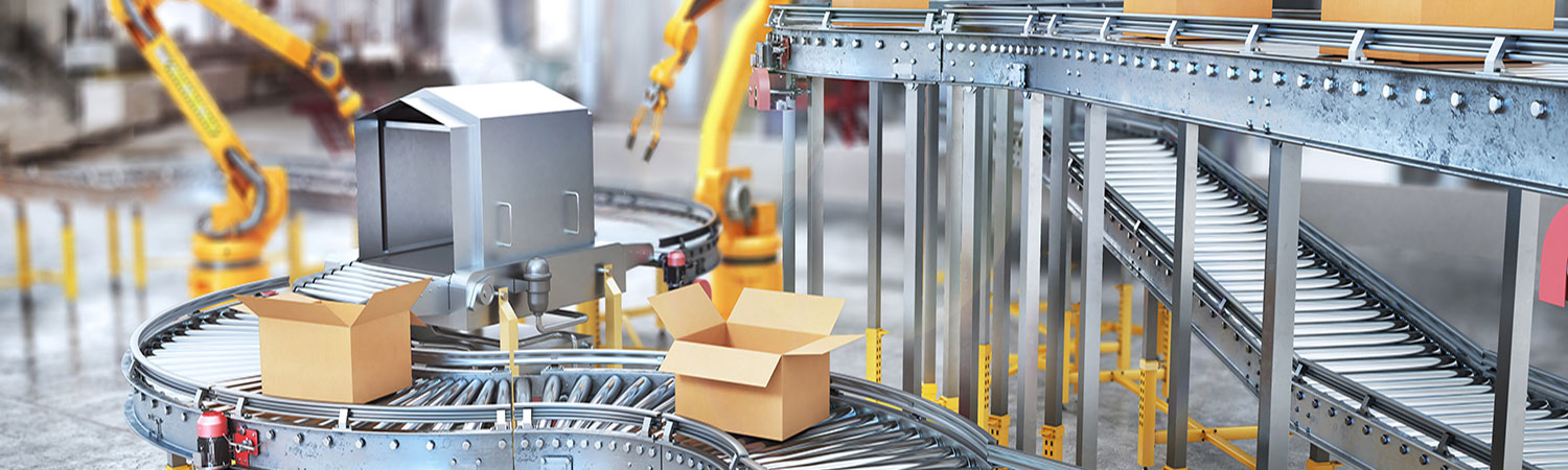
Lebensmittel & Getränke / Verpackung
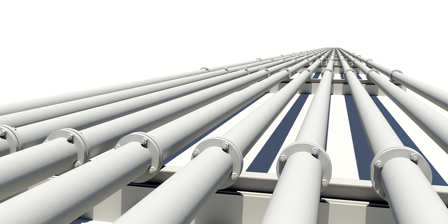
Öl- und Gasindustrie
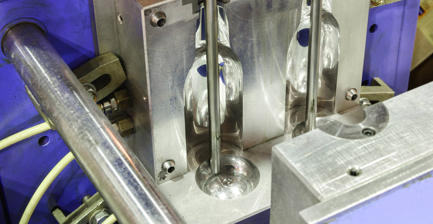
Kunststoffe
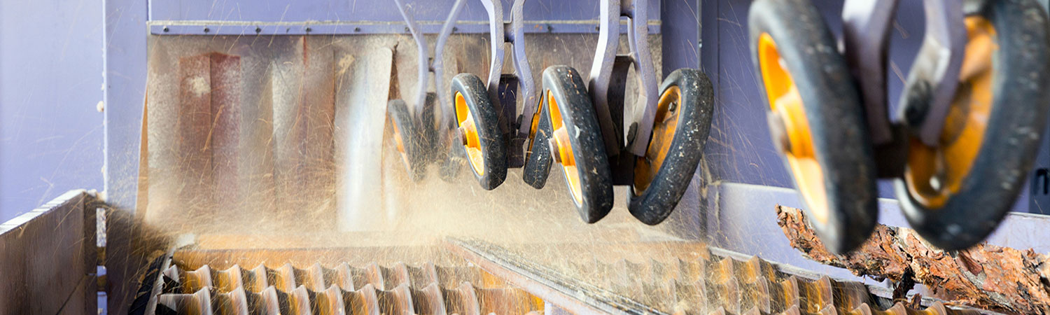
Fortstwirtschaft
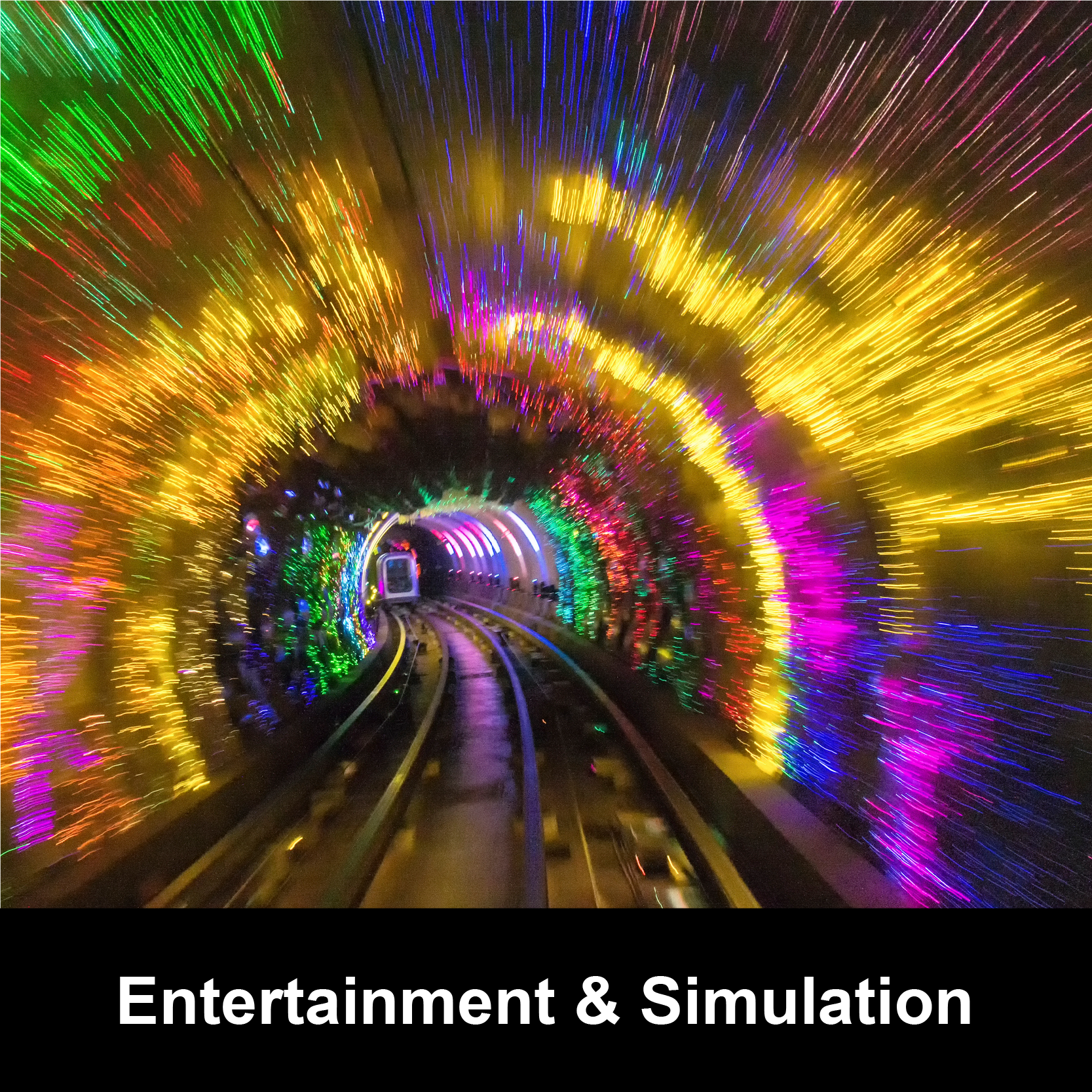
Unterhaltung / Simulation
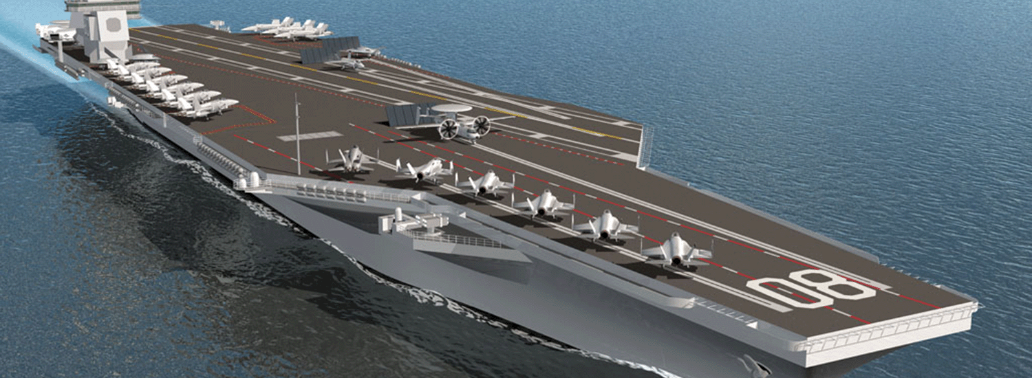
Sonstige Branchen