Tritex TDX DC Linear Actuator
TDX horizontal
TDX Back
previous
next

Tritex TDX DC Linear Actuator

Intelligent Drive | Motor | Actuator

Industrial - Exlar

  • 生命周期状态: 生命周期结束
  • 宣布停产日期
  • 有关更多信息,请联系您当地的销售代表
  • Compact, stand-alone solution. 
  • Simple and intuitive software for mechanical configuration
  • Continuous force up to 872 lbf (3879 N). 
  • Speeds up to 33.3 in/s (846 mm/s). 
  • Strokes lengths up to 450 mm (3 to 18 in). 
  • Voltage classes from 12 to 48 Vdc. 
  • Flexible mounting and accessory options. 
  • Available Class I Division II (C1D2) options
More Details

Overview

Tritex TDX DC Linear Actuator

Quick Data
ModelsFrame Size mm (in)Stroke inPeak Force kN (lbf)Max Continuous Force kN (lbf)Max Speed mm/s (in/s)
TDX06060 (2.36)
3, 6, 10, 12
2.96 (666)
2.4 (528)847 (33.33)
TDX07575 (2.95)
3, 6, 10, 12, 14, 18
5.3 (1,190)
3.9 (872)635 (25)

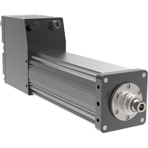
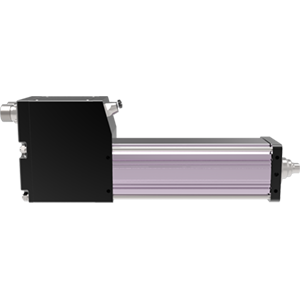
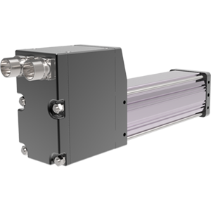
Compact intelligent DC linear actuator, innovative and precise

The Tritex II DC-powered unit houses a servo drive, digital positioner, and electric actuator all in one compact package. These advanced linear actuator cylinders offer the highest power density and smallest footprint servo drive devices on the market. Their small size and innovative design make it easy to incorporate a fully electronic solution in the space of your existing hydraulic or pneumatic cylinder. Tritex II Series actuators integrate a DC-powered servo drive, digital position controller, brushless motor, and linear actuator in a compact, sealed package. Now you can precisely control motion and solve your application requirements with a single, intelligent DC-powered actuator.


DC Linear Actuator Benefits

Power, Performance, and Reliability

With continuous force to 872 lbf (3879 kN), peak force up to 1190 lbf (5293 kN) and maximum speed to 33 in/s (800 mm/s), the Tritex II DC linear actuators offer a robust and superior solution. The DC power electronics provide maximum reliability over a wide range of ambient temperatures (-40 to +65 degrees Celsius). With their 750W servo amplifier and roller screw design, these actuators are top performers. Standard features such as the analog following for position, compound moves, chaining, and individual force/torque control put you in the driver seat.


Compact Package and Low Operating Costs

Tritex II is a robust solution with a small form factor that consistently delivers exceptional reliability and performance. Since the electronics and mechanics are housed in a single, sealed package, space requirements and wiring are minimized. Also, the integrated design eliminates labor costs associated with panel mounting and wiring. At the same time, it eliminates costly and high-maintenance servo cables while resolving troublesome signal strength issues.


Other Advantages

  • Maximum power, precision, and speed in a compact package
  • Superior replacement for pneumatic and hydraulic cylinders
  • IP66S rated for use in harsh environments
  • Roller screw design eliminates the need for inferior ACME and ball screw solutions
  • Programmable software enables automated sequencing
  • Multiple feedback types to best suit your application
  • Seamless integration with your control architecture and processes
  • Engineered for closed-loop servo systems
  • 100% duty cycle for hundreds of millions of strokes
  • Sealed housing for extended life and reduced maintenance


DC Linear Applications Perfect for the Tritex TDX

Electric actuators are used in various medical applications, ranging from simple applications to more complex applications that require more significant force, speed, and control from the actuator. An example of a standard, low-end performance actuator application is a simple hospital bed adjustment. The electric actuator applies minimal force to adjust the bed height up or down to accommodate operator and patient use. In addition to simple applications, electric actuators also are used for high-performance applications such as volumetric filling and fluid dispensing, which require higher forces and high cycle rates. For example, consider an application in which the electric actuator is used as a piston pump to inject fluid into the patient. Before patients receive treatments, operations, medical imaging tests, dyes, or other media are injected to help detect abnormalities. To successfully inject the media, the electric actuator must be compact, produce a high force to create sufficient pressure, and maintain accurate velocity for a consistent injection rate.

If the actuator does not produce enough force, the injection volume will not be correct, resulting in potential harm to the patient and possible failure of the subsequent test. The combination of elevated forces and velocity control produces better results for the doctors and an easier procedure for the patients. Other higher performance applications include laser positioning, which requires high precision, and ultrasonic welding, which requires stability, accurate position, and velocity control. Precision position, velocity control, and force sensing allow electric actuators to perform these applications effectively.


Integration is key

With enhanced features, electric actuators have become a primary option for medical applications. Today, electric actuators offer more power, force, load capabilities, and control than earlier versions, with other advancements including smaller size and integration of power and control components. With advances in technology, electric actuators can deliver higher forces, with load ratings to 100,000 lbs. and above. In meeting requirements for applications requiring high-load capacities, electric actuators still offer position and velocity control, including high-capacity presses and injection molding for medical products. Many electric actuators now integrate the motor and linear actuator into one package, reducing the overall size of the actuator. Instead of combining the size of the motor and actuator, the latest versions feature a compact size of only the motor. The smaller footprint allows them to be designed into compact medical equipment, providing the manufacturer with advantages offered by a more compact product. 

Ergonomics and safety issues can also be reduced through the smaller size. In addition to a compact design, electric actuators now offer electric controls and power circuitry integrated within the actuator. Earlier versions require separately mounted controls and power amplifiers. Now, the actuator, drive, and control are completely integrated into one piece of equipment, eliminating the need for additional power supplies, separate power amplifiers, and expensive cables. This allows the manufacturer to distribute the entire motion system within their mobile medical device and not be tethered to a stationary electrical cabinet.

Electric actuators also produce less noise than their fluid-power counterparts, resulting in a better experience and smoother operation for the doctors and patients. Since the equipment is often located close to the patient, the equipment must operate quietly to reduce patient anxiety levels.


Looking ahead

Electric actuator advancements are changing how medical equipment designers view equipment designs. Many medical institutions are now demanding more compact sizes and more power. Integrating all of the components of a motion system within the actuator package is only the first step to the future design of electric actuators. As technology advances, designers will continue to expand electric actuators capabilities, delivering more force, speed, and control in a single, compact package.

Related Industries

Quick Data
Models:TDM60, TDM75 (standard capacity actuators) – Legacy product
TDX60, TDX75 (high capacity actuators)
Frame Sizes:2.4, 3 in (60, 75 mm)
Stroke Length:3, 6, 10, 12, 14, 18 in (76, 152, 254, 305, 356, 457 mm)
Linear Speed:up to 33.3 in/s (846 mm/s)
Continuous Thrust Capacity:up to 872 lbf (3879 N)
Standards/Ratings:CE; UL 508 C Type 4 Enclosure; CSA 139; CSA Class I Division 2 Groups A, B, C, and D; IP65S standard, IEC 61800-5-1 safety standard for drives

Actuator Type
TDX = Tritex II Linear Actuator, high mechanical capacity

BBB = Actuator Frame Size
060 = 60 mm
075 = 75 mm

CC = Stroke Length
03 = 3 inch (76 mm)
06 = 6 inch (152 mm)
10 = 10 inch (254 mm)
12 = 12 inch (305 mm)
18 = 18 inch (457 mm) (75 mm only)

DD = Screw Lead (linear travel per screw revolution)
01 = 0.1 inch (2.54 mm)
02 = 0.2 inch (5.08 mm)
04 = 0.4 inch (10.16 mm) (60 mm only)
05 = 0.5 inch (12.7 mm) (75 mm only)

E = Connections
G = Standard Straight Threaded Port with internal terminals, M20x1.5 (75 mm only)
N = NPT Threaded Port via Adapter with Internal Terminals, 1/2” NPT (75 mm only)
I = Intercontec Style - Exlar standard, M23 Style Connector

F = Mounting
C = Rear Clevis
G = Metric Rear Clevis
D = Double Side Mount
K = Metric Double Side Mount
E = Extended Tie Rod
M = Metric Extended Tie Rod
F = Front Flange
R = Rear Flange
T = Side Trunnion
Q = Metric Side Trunnion

G = Rod End
M = Male US Standard Thread1
A = Male Metric Thread1
F = Female US Standard Thread1
B = Female Metric Thread1

HH = Feedback Type
HD = Analog Hall Device
IE = Incremental Encoder, 8192 count resolution
AF = Absolute Feedback9

III-II = Motor Stator, All 8 Pole 
TDX060 Stator Specifications
1B8-50 = 1 Stack, 48 Vdc, 5000 rpm
2B8-50 = 2 Stack, 48 Vdc, 5000 rpm
3B8-40 = 3 Stack, 48 Vdc. 4000 rpm2

TDX075 Stator Specifications
1B8-30 = 1 Stack, 48 Vdc, 3000 rpm
2B8-30 = 2 Stack, 48 Vdc, 3000 rpm
3B8-20 = 3 Stack, 48 Vdc, 2000 rpm2

JJJ = Voltage
048 = 12-48 Vdc

KKK = Option Board
SIO = Standard IO
IA4 = +4-20 mA Analog I/O
EIP = SIO plus EtherNet/IP with M12 connector
EIN = SIO plus EtherNet/IP without M12 connector7
PIO = SIO plus PROFINET IO with M12 connector
PIN = SIO plus PROFINET IO without M12 connector7
TCP = SIO plus Modbus TCP with M12 connector
TCN = SIO plus Modbus TCP without M12 connector9

MM = Mechanical Options3
AR = External Anti-rotate
L1/2/3 = External Limit Switches4
RB = Rear Brake
PB = Protective Bellows6
SR = Splined Main Rod5, 8 

Standard Features
Analog and digital I/O
Built-in positioner
Internal terminals accessible through removable cover
Threaded ports for cable glands
M12 connector for Ethernet options (EtherNet/IP, PROFINET, Modbus TCP)
RS485 port (M8), Modbus RTU (opto-isolated)


NOTES:
 1. Chrome-plated carbon steel. Threads not chrome-plated.
 2. Not available on 0.1 inch lead.
 3. For extended temperature operation consult factory for model number.
 4. Limit switch option requires AR option.
 5. This option is not sealed and is not suitable for any environment in which contaminants come in contact with actuator and may enter the actuator.
 6. Not available with extended tie rod mounting option.
 7. Requires customer supplied Ethernet cable through I/O port for Class 1 Division 2 compliance only.
 8. Consult Exlar if ordering splined stainless steel main rod.
 9. When ordering a TDM, RDM or RDG 60 mm or other sizes with top mounted connectors the battery backup for AF feedback must be mounted externally. A DIN rail mounted board (Exlar PN 48224) and battery (PN T2BAT2) are supplied.

* Some options are not available with every configuration. For options or specials not listed above contact your local Exlar representative.

AR = External Anti-rotate Assembly
This assembly restricts the actuator output rod from rotating when the load is not held by another method. Shorter actuators have a single anti-rotation mechanism; longer lengths have a mechanism on both sides.

L1, L2, L3 = Adjustable External Travel Switch(es)
External travel switches indicate travel to the controller and are adjustable for either the home or end position.

RB = Rear Electric Brake
This is a rear, internal holding brake. The rear brake is spring activated and electrically released.

SR = Splined Main Rod
A ball spline shafting main rod with a ball spline nut that replaces the standard front seal and bushing assembly. This rod restricts rotation without the need for an external mechanism. The rod diameter will be the closest metric equivalent to our standard rod sizes. Since this option is NOT sealed, it is not suitable for environments in which contaminants may enter the actuator.

Note: Adding this option affects the overall length and mounting dimensions.

Product Specifications

TDX060 Performance SpecificationsOpen arrow

TDM/X060 Mechanical Specifications

  UNITS 0.1 INCH LEAD
    1 Stack 2 Stack 3 Stack
Continuous Force lbf (N) 339 (1508) 528 (2349) N/A
Peak Force lbf (N) 641 (2851) 666 (2963) N/A
Max Speed @ 48 VDC in/sec (mm/sec) 8.33 (211.6) 8.33 (211.6) N/A
TDX - C_a 
(Dynamic Load Rating)
lbf (N) 2075 (9230) 2075 (9230) NA
TDM*** - C_a 
(Dynamic Load Rating)
lbf (N) 1568 (6970) 1568 (6970) NA
  UNITS 0.2 INCH LEAD
    1 Stack 2 Stack 3 Stack
Continuous Force lbf (N) 180 (801) 280 (1246) 347 (1544)
Peak Force lbf (N) 340 (1512) 354 (1575) 454 (2019)
Max Speed @ 48 VDC in/sec (mm/sec) 16.67 (423.4) 16.67 (423.4) 13.33 (338.6)
TDX - C_a 
(Dynamic Load Rating)
lbf (N) 1540 (6850) 1540 (6850) 1540 (6850)
TDM*** - C_a 
(Dynamic Load Rating)
lbf (N) 1219 (5422) 1219 (5422) 1219 (5422)
  UNITS 0.4 INCH LEAD
    1 Stack 2 Stack 3 Stack
Continuous Force lbf (N) 95 (423) 148 (658) 184 (818)
Peak Force lbf (N) 180 (801) 187 (832) 240 (1068)
Max Speed @ 48 VDC in/sec (mm/sec) 33.33 (846.6) 33.33 (846.6) 26.67 (677.4)
TDX - C_a 
(Dynamic Load Rating)
lbf (N) 1230 (5471) 1230 (5471) 1230 (5471)
TDM*** - C_a 
(Dynamic Load Rating)
lbf (N) 738 (3283) 738 (3283) 738 (3283)
  UNITS UNIVERSAL SPECIFICATIONS
Speed RPM @ 48 VDC 5000 5000 4000
Drive Current @ 
Continuous Force
Amps 14.75 21.5 21.5
Available Stroke Lengths in (mm) 3 (76), 6 (152), 
10 (254), 12 (305)
   
Inertia (zero stroke) lb-in-s^2/ Kg-m^2 0.0007758 
(0.0000008766)
0.0008600 
(0.0000009717)
0.0009442 
(0.000001067)
Inertia Adder (per unit of stroke) lb-in-s^2/in/ Kg-m^2/in 0.00004667 
(0.00000005273)
0.00004667
(0.00000005273)
0.00004667
(0.00000005273)
Inertia Adder (per unit of stroke) lb (kg) 4 lbs – 3 in stroke, 1 stack, 
add 1 lb per inch of stroke, 
add 3 lbs per stack, 
add 3 lbs for brake.
(1.8 kg – 75 mm stroke, 1 stack, 
add 0.5 kg per 25 mm of stroke, 
add 1.4 kg per stack, 
add 1.4 kg for brake.)
Operating Temperature Range** -20 to 65˚ C (-40˚C available, consult Exlar)
Maximum Continuous 
Power Supply Current*
Amps 11 15 15

*Power supply current is based on software current limit, not thermal limit. Consideration for peak current should also be considered when sizing power supplies.
**Rating based on 40˚ C ambient conditions. 
*** Legacy Product

TDX075 Performance SpecificationsOpen arrow

TDM/X075 Mechanical Specifications

  UNITS 0.1 INCH LEAD
    1 Stack 2 Stack 3 Stack
Continuous Force lbf (N) 613 (2727) 872 (3879) NA
Peak Force lbf (N) 884 (3932) 1190 (5293) NA
Max Speed @ 48 VDC in/sec (mm/sec) 5.00 (127) 5.00 (127) NA
TDX - C_a 
(Dynamic Load Rating)
lbf (N) 5516 (24536) 5516 (24536) NA
TDM*** - C_a 
(Dynamic Load Rating)
lbf (N) 3310 (14724) 3310 (14724) NA
  UNITS 0.2 INCH LEAD
    1 Stack 2 Stack 3 Stack
Continuous Force lbf (N) 347 (1544) 494 (2197) 774 (3443)
Peak Force lbf (N) 501 (2229) 674 (2998) 1095 (4871)
Max Speed @ 48 VDC in/sec (mm/sec) 10.00 (254) 10.00 (254) 6.67 (169.4)
TDX - C_a 
(Dynamic Load Rating)
lbf (N) 5800 (25798) 5800 (25798) 5800 (25798)
TDM*** - C_a 
(Dynamic Load Rating)
lbf (N) 3570 (15880) 3570 (15880) 3570 (15880)
  UNITS 0.5 INCH LEAD
    1 Stack 2 Stack 3 Stack
Continuous Force lbf (N) 147 (654) 209 (930) 328 (1459)
Peak Force lbf (N) 212 (943) 286 (1272) 464 (2064)
Max Speed @ 48 VDC in/sec (mm/sec) 25.00 (635) 25.00 (635) 16.67 (423.4)
TDX - C_a 
(Dynamic Load Rating)
lbf (N) 4900 (21795) 4900 (21795) 4900 (21795)
TDM*** - C_a 
(Dynamic Load Rating)
lbf (N) 3016 (13416) 3016 (13416) 3016 (13416)
  UNITS UNIVERSAL SPECIFICATIONS
Speed RPM @ 48 VDC 3000 3000 2000
Drive Current @ 
Continuous Force
Amps 18.5 22.5 22.5
Available Stroke Lengths in (mm) 3 (76), 6 (152), 10 (254), 12 (305), 14 (356), 18 (457)
Inertia (zero stroke) lb-in-s^2/ Kg-m^2 0.01132 (0.000012790) 0.01232 (0.00001392) 0.01332 (0.00001505)
Inertia Adder 
(per unit of stroke)
lb-in-s^2/in/ Kg-m^2/in 0.0005640 (0.0000006372)
Approximate Weight lb (kg) 11 lbs – 3 in stroke, 
add 1 lb per inch of stroke, 
add 3 lbs per stack, 
add 3 lbs for brake.
(5 kg – 75 mm stroke, 1 stack, 
add 0.5 kg per 25 mm of stroke, 
add 1.4 kg per stack, 
add 1.4 kg for brake.)
Operating Temperature Range** -20 to 65˚ C (-40˚C available, consult Exlar)
Maximum Continuous 
Power Supply Current*
Amps 15 18 18

*Power supply current is based on software current limit, not thermal limit. Consideration for peak current should also be considered when sizing power supplies. 
**Rating based on 40˚ C ambient conditions.
*** Legacy Product

Product Literature

Catalogs, Brochures, and Success Stories

Industrial - Exlar, Brochures/Catalogs
Industrial - Exlar, Success Stories
Previously performed by pneumatics, our Tritex Series actuators were able to achieve more accuracy, repeatability, and longer life in a smaller space. Giving the customer exactly what they wanted.
Industrial - Exlar, Success Stories
The Tritex II actuators were easily integrated into Seattle Chocolates existing PLC system and allowed them to pre-program multiple settings for their various product recipes.
Industrial - Exlar, Success Stories
Exlar provided an alternative to the existing hydraulic actuators used on refined product pipelines. Tritex II actuators simplified Cenex’s installation and provided a more cost-effective solution.
Show Resources

Actuator Technical Data

Manuals, Technical Tips, and Software

Industrial - Exlar, Manuals
Industrial - Exlar, Software & Downloads
Industrial - Exlar, Manuals
Show Resources

Videos

Industrial - Exlar, Product Videos
Our Automotive Factory Floor Solutions animation shows our FTX, GTX, GTW, and TTX actuators and where they can help factories worldwide.
Industrial - Exlar, Product Videos
Learn how we build our actuators
Industrial - Exlar, Product Videos
Exlar® actuators from Curtiss-Wright are an industry leader in electric actuation. Our research, pride, and creativity shine in this short video as we highlight our top product lines.
Industrial - Exlar, Product Videos
Ever wonder about the benefits of changing your system from hydraulic cylinders to electric actuation. We have the information you need.
Show Resources

Find more resources in our InfoCenter.  

How can we help?

Can the Tritex II linear actuators replace hydraulic cylinders?Arrow
Tritex actuators have similar capabilities as a comparably sized hydraulic cylinders but without the cost or maintenance issues. High force, fast speeds, and precise movements make it a superior substitute for hydraulic applications
Does the AC Linear Actuator make an ideal hydraulic replacement?Arrow
Tritex actuators have the same capabilities as a hydraulic equivalent but without the cost or maintenance issues. High force, fast speeds, and precise movements make it a superior substitute for hydraulic applications.
Is the Tritex Series an Industry 4.0 IoT actuator?Arrow
The Tritex II Series actuators are intelligent actuators incorporating on-board control and communications capabilities, enabling support for distributed control and IIoT architectures
  • Production Efficiencies (speed, up-time, duty cycle)
  • Environmental Sustainability (energy efficiency, reduction in hazardous materials)
  • Agile & Adaptable Processes (configurability, connectivity)
  • Fully Autonomous Operation (distributed control, predictive maintenance)
What are the primary benefits of using an electric actuator system over hydraulics?Arrow
Electric actuators offer high speed and force, are flexible and easily programmable for a variety of load conditions, have high accuracy and repeatability, are efficient, simple to install, require little maintenance, and are environmentally friendly.

By not using a hydraulic system, the user can eliminate oil leaks, reduce pollution, and improve worker safety. Electric actuators are also a non-toxic solution, especially in the food industry

This site uses cookies to improve our service, you can find out more here - for the best web experience please accept cookies

x