
Exlar Products
Universal Linear Actuators
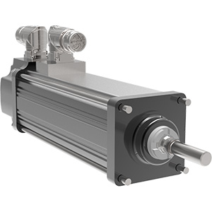
Integrated Motor | Actuators
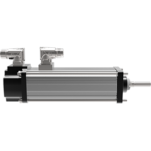
Intelligent Drive | Motor | Actuators
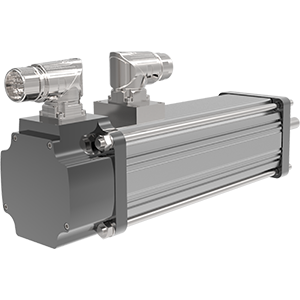
Rotary Actuators
Exlar Legacy Product Support
Industries
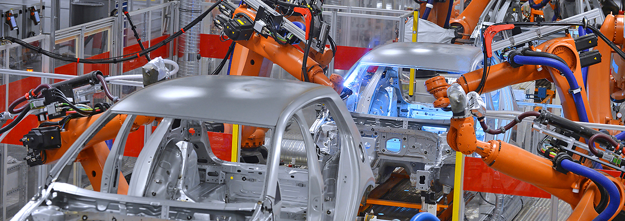
Automotive / Tire
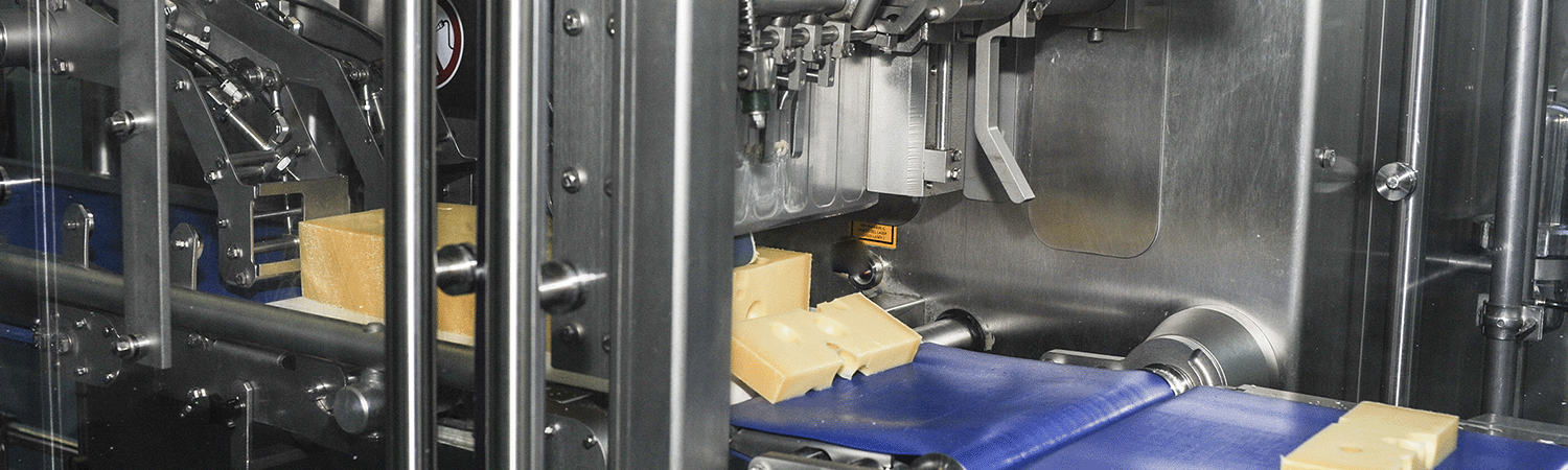
Food & Beverage / Packaging
Oil & Gas
Plastics
Forestry
Entertainment / Simulation
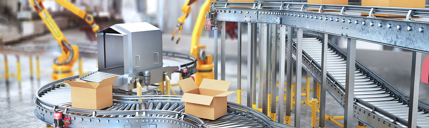
Other Industries


-Order.jpg "GSX-(H)-Order.jpg")


.png "GSX50-0-2-lead-(1).png")


